6421 North Nirvana Place Tucson, AZ 85750 USA. Tel: 520.270.8086
E-mail : araca@aracainc.com
The Solid State Technology Article
In the December 2009 issue of Solid State Technology, along with my co-authors Ara Philipossian of the University of Arizona and Araca Incorporated, and Michael Goldstein of Intel, I published an article projecting what might be expected to go right or wrong during CMP when the wafer size is increased to 450 mm. Since 450 mm wafers were rare at the time (we had one at Araca) and there were no commercial 450 mm polishers, the article was based totally on mathematical modeling and numerical simulations. The article analyzed several important questions, such as how much slurry one should use on the larger polishing pad and what kind of temperature rise should be expected. In order to make this discussion self-contained and to save the reader the pain of locating the original article, I’ll summarize the methods and findings here. I will also add some analysis that was not in the original article.
Methodology
Since no commercial 450 mm polisher designs existed at the time, we decided to assume that any emerging tool would be an extension of the most common current technology; namely, that whatever it was, it would be a rotary tool with a single polishing head engaging with the platen. Since all single head rotary polishers are similar geometrically, this allowed the use of scaling. The basic idea of scaling is to convert a problem in which physical quantities that have dimensions, such as length and speed, into one in which everything is dimensionless. Done consistently, a 200 mm polisher will have basically the same scaled geometry as a 300 mm polisher, and this common geometry will also be the scaled geometry of a 450 mm polisher. For example, if all horizontal distances on a polisher plan are divided by the platen radius R, then the scaled plans for all 3 tools will have a scaled platen radius of 1. This commonality makes it possible to use knowledge about existing polishers to understand what to expect for a 450 mm tool.
Slurry Flow Rate
One of the most basic questions about 450 mm is how much slurry to use. The answer to this question affects the cost of running a 450 mm tool and it also affects the temperature of the tool since slurry is a coolant. In the SST article, we used the thin film equation to model slurry flow. The thin film equation is a simplification of the more comprehensive but also more complex Navier-Stokes equations. It is a mass conservation law that relates the rate of change of the local fluid thickness at a point on the pad surface to the mean flow velocity at that point. The thin film equation is a good approximation to the Navier-Stokes equations when the fluid film is thin relative to the horizontal dimensions and the fluid flows over a smooth surface. In CMP, the slurry film thickness is always small relative to the pad diameter (one should hope) but the pad surface smoothness assumption can be questioned because of grooving. The analysis that we did is therefore most appropriate for pads with little or no grooving, but in any case, we expected the thin film equation to provide some rough guidance.
As in the case of the polisher geometry, we obtained general results for all polishers by scaling the thin film equation. Using the horizontal geometry scaling by the platen radius R described above, we did the same scaling of the horizontal variables x and y in the thin film equation. Since the equation is time-dependent, we also needed a time scale. A natural scale is to divide the time by the platen rotational period, or equivalently to multiply it by the rotation rate W. These two choices then mandated a velocity scale of RW. Finally, we also needed a scale for the local fluid film thickness. This can be picked independently of the horizontal scale, so we used the pad roughness, which is comparable in magnitude to the fluid thickness. The thin film problem then becomes the same for all polisher sizes, with the platen having a radius of 1, a rotational period of 1, and a maximum speed of 1 at the platen perimeter. This holds regardless of the actual physical dimensions of the platen or the actual rotation rate.
What does all of this have to do with the slurry flow rate? Well, the thin film equation has a boundary condition where the slurry is applied. The boundary condition involves the flow rate F. Just as the horizontal length scale and time scale mandated the velocity scale RW, the scaling choices that have already been made tell us how to scale the flow rate. The mandatory scale for the flow rate turns out to be R 2W. That is the flow rate should scale like the product of the pad area, the platen rotation rate and the pad surface roughness. Notice that this product has units of volume per unit time, so the scale can be thought of as a reference flow rate.
What are we trying to achieve with a 450 mm tool? In the SST article, we assumed that whatever process is being run, the user is trying to achieve the same polishing result at 450 mm as on a 300 mm tool, but with a larger wafer with more die. Among other things, this means keeping the polish rate the same on the new and old tools. Using Preston’s law, a constant polish rate can be maintained by using the same pressure and the same relative sliding speed between the wafer and the pad. Since the distance of the wafer center from the platen center should be larger on a 450 mm tool than on a 300 mm tool, this implies that for a given process, the 450 mm platen should run slower to achieve the same result. This can be simply quantified when the platen and head rotate at the same rate, or at nearly at the same rate, as is the case for most commercial processes. If the wafer-platen center distance is d1 on one of the tools and d2 on the other and the rotation rates are W1 and W2, then the relative sliding speed and thus the polish rate (at constant pressure) is constant when d1 W1 = d2 W2.
The flow rate scaling and the constant removal rate assumption lead to a very simple scaling law. Flow rate scaling says that the flow rates F1 and F2 on two different rotary tools should be chosen so that
F2 / F1 = [σ2 (R2) 2 Ω2] / [σ1 (R1) 2 Ω1] .
If the pads on the two tools have comparable surface roughness, then the constant removal rate assumption implies that
F2 / F1 =(R2) 2/ (R1) 2× d1 / d2 .
The flow rate should then scale like the ratio of the pad areas times the inverse ratio of the wafer-platen center distances. This is the basic result of the analysis underlying the SST article.
We can see what this result means better using some specific numbers. In 2009, the proposed diameter of the platen for a 450 mm tool was 1092 mm or 43”. For 200 mm and 300 mm, platen diameters vary a little, but for comparison we used 508 mm (20”) and 762 mm (30”). We assumed that all pads have a 50.8 mm (2”) diameter un-grooved area in the center and that the mean location of the head center was in the middle of the grooved part of the pad. This would place the head center at 139, 203 and 286 mm, respectively. On a 200 mm commercial polisher, it is not unusual to use a flow rate of around 150 ml/min. The scaling law then says that the flow rate on a 300 mm polisher should be about 231 ml/min. This is not far from common practice and serves as a check on the analysis. On a 450 mm tool, the scaling law predicts that the flow rate for comparable operation be about 339 ml/min.
We can contrast this prediction with a less sophisticated estimate based on platen area alone. Using this measure, a 300 mm tool would require 338 ml/min if a 200 mm tool uses 150 ml/min, and a 450 mm tool would need a whopping 693 ml/min. Hopefully, the thin film equation estimate will prove correct with time.
Temperature
Understanding how the polishing temperature on a 450 mm tool will differ from a smaller tool is fairly complicated, but there is a simple way to see what the ballpark result will be. During polishing, the local heating rate depends on the dissipated power per unit area (power density) at the pad-wafer interface. The power density is proportional to PV, where P is the pressure and V is the relative sliding speed. Since Preston’s law says that the removal rate is also proportional to PV and we are trying to maintain the same removal rate across polishers, it follows that the power density and thus the heating rate should be roughly constant. So, we don’t expect a 450 mm polisher to be hotter than a 300 mm polisher under comparable operation.
A more sophisticated thermal analysis was done for the SST article using a three-dimensional time-dependent finite element model that includes heat transport and conduction by the pad, the slurry, the polishing head, the retaining ring and wafer, and some of the internal heat conducting structures in the head. We had to guess what the latter might be for 450 mm based on the little we knew about 200 and 300 mm tools. Before doing the thermal modeling, we simulated the steady state slurry flow over the rotating pad from the injection point at the flow rate indicated by the scaling law. The slurry model included the effects of pad roughness, the accumulation and transport of slurry in the bow wave at the head leading edge, the loss from the pad, and slurry transport in the gap between the wafer and the pad. All of this was done either with the thin film equation in areas where the slurry has a free surface, or with its cousin the Reynolds equation between the wafer and pad. The numerical method that was used provided a seamless interface between different parts of the model with nearly perfect conservation of mass. In any case, the slurry film typically reached steady state within a few pad rotations. Since slurry absorbs and transports heat, obtaining this solution was a prerequisite for accurately modeling the temperature rise for different size tools.
OK, so what did we find? Figures 1 and 2 show the calculated pad surface temperatures at the center of the wafer track slightly in front of the head (and outside of the bow wave), slightly behind the head, and at the center of the head for a 300 mm model and a 450 mm model. The pad temperature rise is about the same for both polisher sizes, confirming the back of the envelope reasoning. Looking in detail, though, the 450 mm pad is predicted to be slightly cooler than the 300 mm pad by about 0.5o C. This difference is a result of having a larger flow rate and a lower rotation rate on the 450 mm tool, factors that we think allow for more heat absorption and transport by the slurry.

Figure 1: Pad temperature increase near the leading edge, trailing edge, and at the center of the head at the middle of the wafer track for a model 300 mm tool.

Figure 2: Pad temperature increase near the leading edge, trailing edge, and at the center of the head at the middle of the wafer track for a model 450 mm tool.
What about the wafer? The wafer temperature can have a major impact on removal rates in copper and tungsten polishing, so we would like for the wafer temperature to be the same for comparable processes. For all three models that we ran, we therefore examined the wafer temperature as a function of distance from the wafer center. We also included the temperature of the retaining ring since a hot ring could presumably transfer heat directly or indirectly to the nearby wafer edge. Figure 3 summarizes what we found for the three model polishers at the end of one minute of polishing. The graph shows that the 450 mm wafer temperature rise is almost identical to the result for 300 mm and that the 450 mm thermal profile is a smooth extension of the 300 mm profile. While we expected fairly good agreement based on the back of the envelope consideration, the closeness of the agreement was a little surprising.
The figure also shows the influence of the retaining ring. We assumed that the retaining ring width was the same for all three models; that is, we guessed that the tool manufacturer would scale up the ring diameter but not the width. The model predicts that the ring has some influence on wafer temperature within one or two cm of the wafer edge with the effect being about the same for 300 mm and 450 mm. On the other hand, for 200 mm the thermal effect of the ring is larger and extends farther from the wafer edge. We attribute this to the fact that the area of the ring is much larger relative to the area of the wafer for 200 mm and the platen rotation rate is much higher. Since the ring material has a higher friction coefficient than the wafer, this situation results in more heat generation around the wafer and faster heat transport to the wafer for 200 mm.
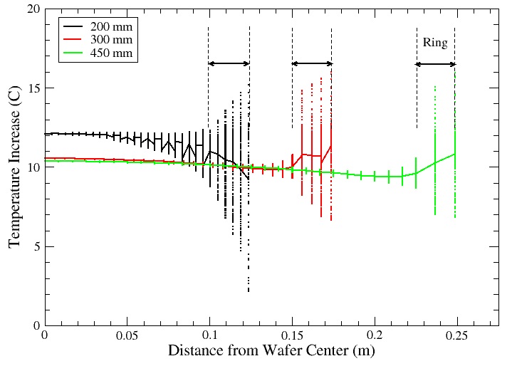
Figure 3: Wafer temperature increase comparison at the end of a one-minute process.
Conditioning
One matter that we did not address in detail in the SST article is pad conditioning. The area of the proposed 450 mm pad is twice as large as the area of a 300 mm pad. Since the processing time would presumably have to be the same if the processes that are run are comparable, the conditioner would have to dress twice as much area in the same time for 450 mm. It was not clear how this would be accomplished. One possibility would be to use a larger conditioner, one roughly six inches in diameter. Other options would be to engineer two conditioners for the platen or to run the sweep of a 4” conditioner much faster to cover more area. While the latter sounds simple, it has its own side effects. We did not attempt to analyze what the best choice might be. Since actual 450 mm polishers now exist in small numbers, it would be interesting to see how the OEMs chose to solve this problem and how successful they were.